KR8 Inverted Front End Installation Guide
FITMENT: 2009 and Up FLHR ROAD KING, FLHT ELECTRA GLIDE, FLTR ROAD GLIDE AND FLHX STREET GLIDE
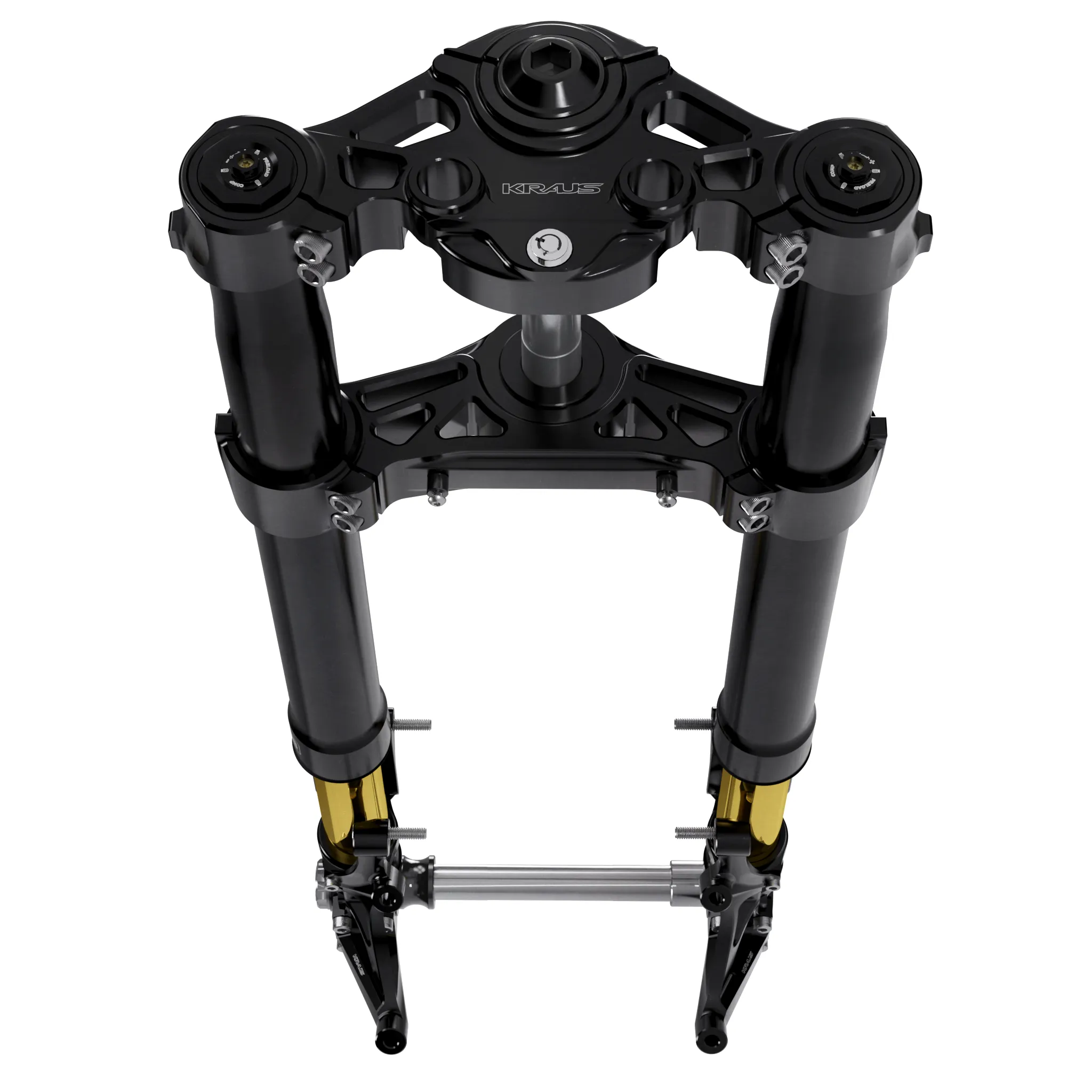
KRAUS Motor Company designs, engineers, tests, and manufactures performance suspension and braking systems for Harley-Davidson™ motorcycles designed to deliver improved road feel in real world punishing riding conditions. KRAUS Sport Touring Packages come complete with a fork stem and all necessary stock hardware and parts to bolt a KRAUS Inverted Front Suspension Package up to your bike. These instructions are meant to be an overview, a guide for the experienced technician. If you do not have prior experience or training installing motorcycle suspension componentry, we strongly recommend that you consider hiring a qualified, experienced technician to install this KRAUS Performance package for you.
About Finishes: Like most finishes, anodizing is delicate and can be scratched. Extra care should be taken during installation and cleaning of all of our parts. Although we use a high grade type 2 anodizing that has UV resistance, anodizing is an organic process/ substance and can fade with excessive sun exposure or be stained with chemicals and cleaners.
Disclaimers:
- This installation may require cutting or drilling factory components. Please read instructions carefully before beginning installation.
- Will require aftermarket 108mm radial brake calipers.
- May Require new front brake lines depending on your choice of caliper.
- Using your factory Nacelle may require modifications such as drilling/cutting, Kraus recommends finding an alternative to the factory nacelle or removing it all together.
- KR8 instructions will begin from the point where the front end of the bike is completely disassembled; front wheel, forks, and trees MUST be removed.
- 21” front wheel will not fit “Standard Length (Touring Valving)” - Fender clearance is limited on 21” front wheel and fender. Outer tube tops must be ush with top of tree during install.
PROJECT DETAILS:
- Time required: One full day for a Sr. Tech.
- Existing Componentry and OEM Fork Set Removal: 1.5 hours
- KRAUS Performance Package install: 4.5 hours
- Validation and Road Test: 1 hour
Tools Required
- Torque wrench
- Allen Key Set: T-handle/ball and regular SAE & Metric
- Socket Set: SAE & Metric
- 2 non-marring wedges
- Bearing Press
STEP 1 - REMOVE YOUR OEM PARTS:
- Fairing
- Dash Panel
- Key Switch
- Front Forks
- Triple Tree…AND…any associated bodywork or accessories.
Remember: Take your time removing all of the controls and bodywork. We recommend covering your tank.
Note: We strongly recommend replacing your neck bearings with new bearings.
STEP 2 - BEGIN INSTALLATION:
FORK PREPERATION:
- Install Brake Caliper mounts onto fork. (See fig. 1)
NOTE: Rebound Fork is intended to be installed on right side of bike while Compression fork is to be installed on the Left, viewed from the seated position of the bike.
Compression fork has “COM” inscribed on top cap; Rebound has “REB” inscribed on top cap. (See fig. 2) - Using supplied hardware from fork component box, begin with the screw position on inner middle hole closest to wheel (See fig. 3), torque to spec, (Upper M6 Screws; 7Nm/62in-lbs), (Lower M8 Screws; 19Nm/170in-lbs). Leave axle screws loose. (See fig. 4)
- Install fork guards (M5 Screws, 4Nm/35in-lbs). (See fig. 5)
Torque Specs:
- Upper M6 Screws: 7Nm/62in-lbs.
- Lower M8 Screws: 19Nm/170in-lbs.
- M5 Screws: 4Nm/35in-lbs.
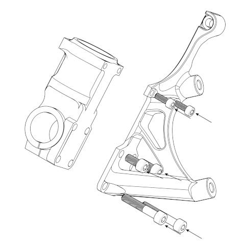
Fig. 1
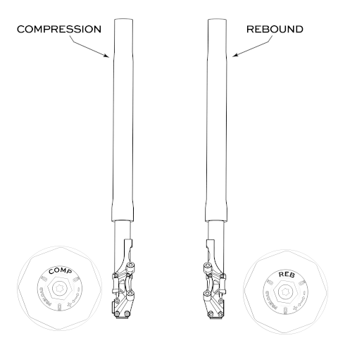
Fig. 2
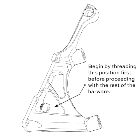
Fig. 3
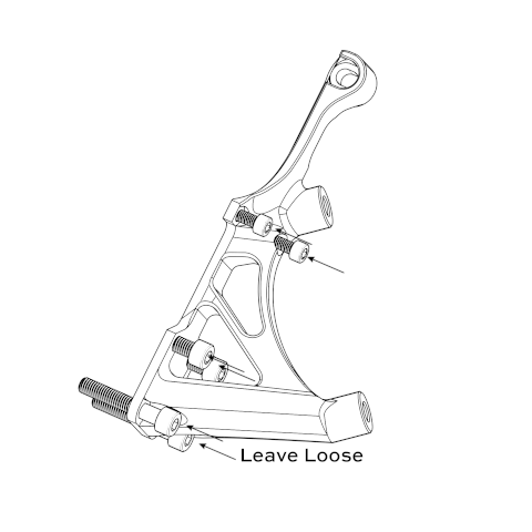
Fig. 4

Fig. 5
INSTALLATION OF TRIPLE TREES:
- Clean/inspect races, bearings & dust shields then grease your bike’s neck bearings for install.
- Install/slide the lower neck bearing dust shield followed by the lower neck bearing onto stem. Press them carefully onto the stem attached to the lower triple tree.
- Press the lower bearing down the stem towards the dust shield until firmly seated at the stem’s base. The bearing should spin freely.
- Apply the specified and appropriate grease to the upper and lower neck bearing races.
- Carefully slide bottom triple tree and stem up through frame neck.
- Carefully place the top neck bearing onto the stem.
- Gently press the upper bearing down the stem towards the fork neck until firmly seated on the top bearing race. The bearing should spin freely. Place top dust shield over the top neck bearing.
- Thread on Yoke Nut until there is good bearing feel. (See fig. 6)
- Slightly loosen yoke nut until no friction is felt.
- Install bars and risers onto top triple tree.
- Install the top triple tree onto yoke nut, ensure that it is seated properly onto the bearing dust shield. Ensure the triple tree moves freely from side to side.
- Ensure top nut is flush with bottom of tree. (See fig. 7)
- Install top nut clamp onto top tree. Tighten screws until lightly seated, so fall away can be set later. (See fig. 8)

Fig. 6
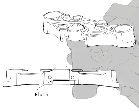
Fig. 7

Fig. 8
INSTALLATION OF FORK LEGS:
IMPORTANT! Not using shims can potentially cause damage or scoring to forks.
- Before installing forks into either Kraus tree, use spreader/shims to open the bore of each tree. (See fig. 9)
- Install each fork leg into trees. (See fig. 10) Ensure pinch bolts are loose. Starting with one side of the triple tree using small flat blade screwdrivers or shims, expand both top and bottom fork clamp pinch bolts slightly. This makes sliding the fork into the triple trees easier, while avoiding damaging the fork legs. Repeat process with opposite side.
- Make sure right and left forks are in their proper position. Riders right side fork is Rebound, left side fork is compression.
- Slide each fork leg upwards into triple trees clamps; avoid scratching the fork tubes. Ensure top triple tree does not lift off the dust shield.
- Adjust the fork tube height in the triple trees so that just the fork cap is protruding above the top triple tree. Push down on top triple tree to make sure the top triple tree has positive contact with the top neck bearing dust shield. Set both forks equal height in triple trees, confirm alignment by sliding the axle into the slider bottoms.
- Make sure axial alignment is correct for proper fork and upper tube clearance.
- Torque bottom Tree pinch screws to 12ft-lbs. Wait until fall away has been set before torquing top tree clamping screws and top nut clamp.
Note: Wheel and axle MUST be installed before setting Fall Away.
Torque Specs:
- Bottom tree pinch screws: 12ft-lbs.
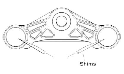
Fig. 9
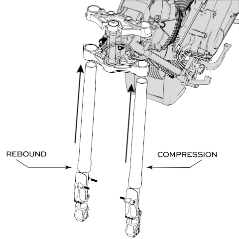
Fig. 10
Fairing Mount Installation - 24+ Street Glide Only
Complete between Step 6 and Step 7 of Fork Leg Installation
Requires separate purchase of Kraus 24+ Street Glide Fairing Mounts
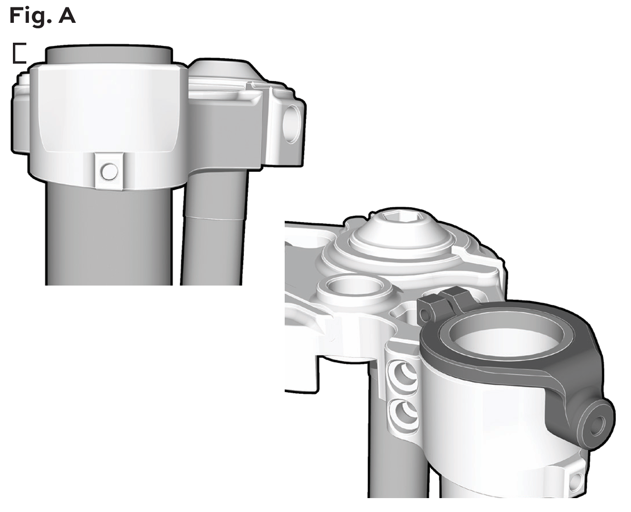
Ensure forks protrude a minimum of ¼'' above the top tree so the top nacelle clamp can be installed (Fig. A).
NOTE: Do not torque until the bottom tree mount is installed on the lower tree.
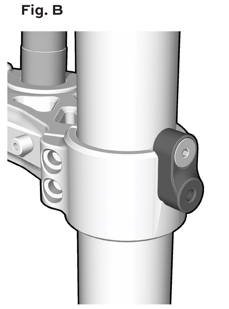
Install lower fairing mount onto bottom tree and torque (11 ft-lbs). Mount should sit tight against bottom tree face and screw should fully tighten (Fig. B).
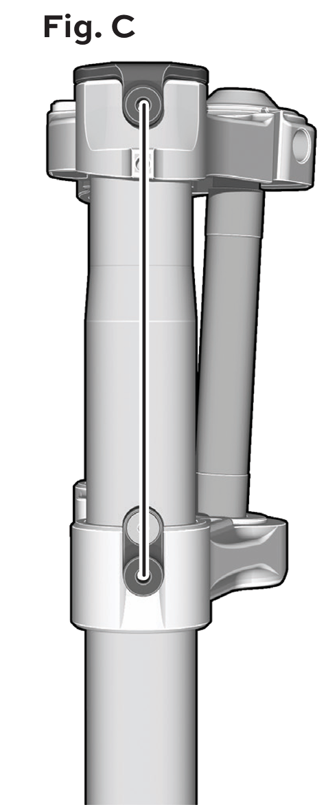
Using the lower fairing mount and existing side holes, ensure the upper fork clamp makes a straight line along the side profile of the trees, then torque to 6 ft-lbs (Fig. C).
Lock Relocation: To use OEM lock and nacelle, bolt heads must be filed down to remove OEM lock from OEM tree. Supplied 10-24 x ¾'' screws can be used to install OEM lock onto Kraus tree.
Veloci Pullback Plate: If a Kraus Veloci Pullback Plate has been previously installed or is currently being installed, alternative Veloci Pullback Plate spacers must be used to be compatible with KR8.
See Veloci Pullback Plate instructions for torque specs and nacelle modification.
NOTE: Setting fall away is recommended before the fairing is installed and before fork pinch clamps are torqued.
→ Return to page 6, Step 7.
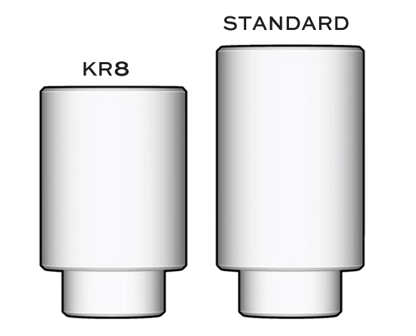
Note: KR8 Veloci Pullback Plate spacers are shorter than standard Veloci spacers.
INSTALLATION OF AXLE:
- Prepare axle for install by lightly coating the surfaces of the axle with anti-seize or grease.
- Slide the axle through the Rebound fork starting with the smaller end. Axle will slide through fork, then wheel, then spacer, then other fork on the other side of the wheel. If your bike does not have ABS, use supplied spacer in this position. Slotted spacer is to be installed flush with the inside of the compression fork. (See fig. 11)
NOTE: Slotted spacer should have slit aligned with bottom slit of fork.
- Slide washer onto end of axle, thread nut onto front axle and torque with pinch bolts loose on bottom of forks (110ft-lbs).
- Torque pinch bolts. (19Nm/170in-lbs)
- With wheel installed, fall away can be set so long as NO additional components interfere with the swing of the front wheel, left to right.
- Mount calipers onto the KRAUS fork lower leg caliper receivers using M10x1.25 bolts. Brake pads must be properly aligned and have full contact potential with rotor friction area. Add caliper mount spacers depending on rotor size.
- Carefully and slowly rotate wheel making sure there are no alignment and clearance issues.
- Install front fender using supplied bolts and black delron spacers. Place the spacers between the fender and the forks. The longer spacers are to be installed in the rear fender mounts. (2013 and earlier model bikes will only have spacers on the rear fender mounts.)
- Again carefully and slowly rotate wheel making sure there are no alignment and clearance issues.
Torque Specs:
- Axle nut: 110ft-lbs.
- Pinch bolts: 19Nm/170in-lbs.
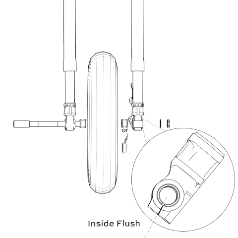
Fig. 11
Setting Fall Away:
- When setting fall away it is important not to use Harley’s Fall Away setting (B). Instead, use the Kraus fall away (A) referenced in Schematic 3.
- Raise the motorcycle so that the front and rear tires are the same distance from the floor.
- Turn the front wheel to the left Fork stop and then let go. The wheel should swing from side to side, finally stopping in the swing specified in schematic 3. If it stops in the lesser number swing it should be at or after the straight-forward position.
- Make sure the clutch cable or main harness is not influencing the swing momentum in any way.
- A steering head that is too tight can interfere with the vehicle’s ability to absorb a weave. A steering head that is too loose can interfere with the vehicle’s ability to absorb a wobble.
- With fall away set, top tree and clamp nut screws can be torqued to spec: (20ft-lbs).
- When installing your brake line, confirm brake lines are proper length and not stressed or stretched whether the front end is compressed or extended.
- Once the front end is installed and tightened up to specifications, you are ready to reinstall all of the components that you removed including any associated bodywork or accessories. We recommend that you refer to your OEM manual for procedure, step by step run through, required tools and specifications.
- After all pieces and parts are properly installed, go for a slow, careful test ride. Afterwords, double check all pieces, parts and systems.
SCHEMATIC 3

24+ FENDER ADAPTERS (SOLD SEPERATELY)
Installing an OEM 2024+ Front Fender:
If you are going to install the OEM Fender on a 2024+ Model, you will need to purchase the Fender Adapter Kit.
These brackets will allow installation for the new bolt pattern on a 24+ Front Fender.
- Install the fender adapters on your 24+ Front Fender (See Fig 12.)
- Tighten the mounting bolts. Torque to 11 -lbs (15N-m) (See Fig 13.)
Install the Fender and Adapters as one on the Forks:
- Line up the mounting holes on the Fender Adapter to the Fork Guard and Brake Caliper Bracket.
- Thread in the mounting bolts and slowly tighten down each side equally. Torque to 11 -lbs (15N-m)
Afer all peices and parts are properly installed, go for a slow, careful test ride. A erwords, double check all pieces, parts and systems.
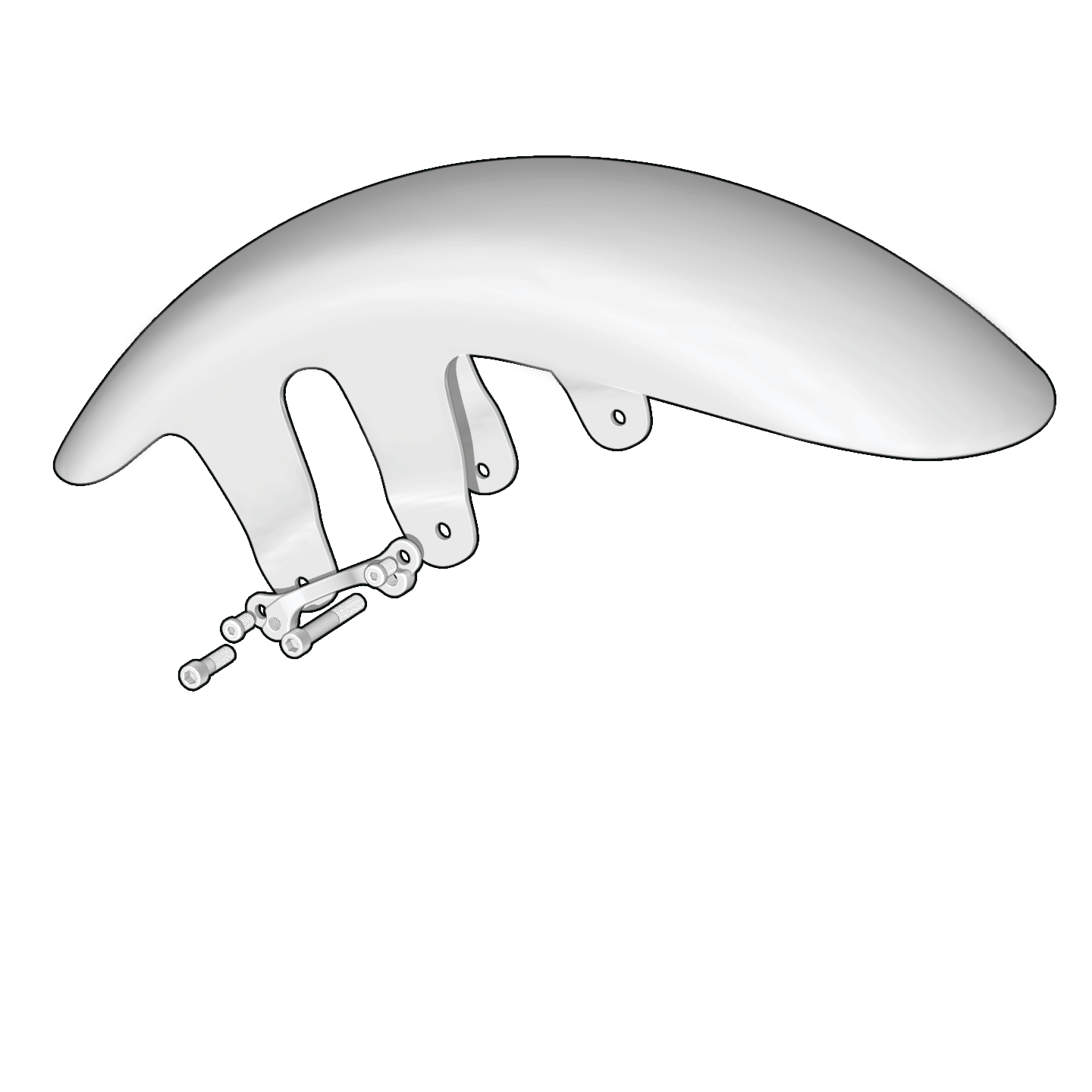
Fig. 12
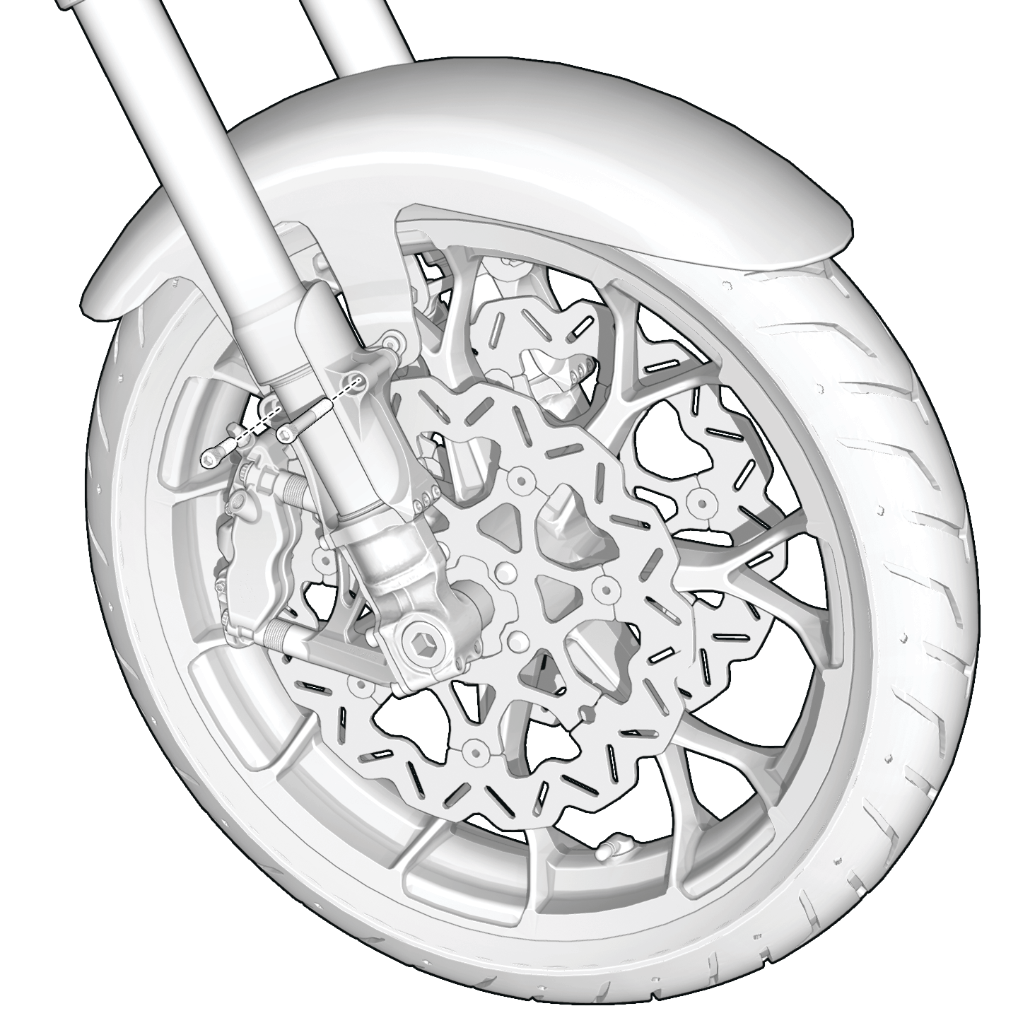
Fig. 13
Check Your Sag Settings!
A proper sag setting can be the difference between good suspension and great suspension:
See below to set your sag based on your weight.
| WEIGHT (LBS) | ||||||||||||||
|---|---|---|---|---|---|---|---|---|---|---|---|---|---|---|
| 130 | 140 | 150 | 160 | 170 | 180 | 190 | 200 | 210 | 220 | 230 | 240 | 250 | ||
| TURNS | KR8 (Standard) | 9.5 | 9.75 | 10 | 10.25 | 10.5 | 10.75 | 11 | 11.25 | 11.5 | 11.75 | 12 | 12.25 | 12.5 |
| KR8 (+2") (14N/mm) |
11.5 | 11.75 | 12 | 12.25 | 12.25 | 12.5 | 12.75 | 13 | 13.25 | 13.5 | 13.75 | 13.75 | 14 | |
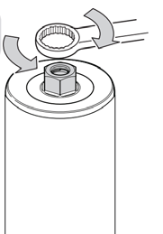
Sag is set by turning your Preload cap adjuster
Counter Clockwise all the way, then turning clockwise
the specific amount according to the chart.
Adjusting Your Suspension
PRELOAD gets your suspension to operate in its ideal range, measured by recording sag. Using our chart should get you to 30mm, which is just about right.
Measuring sag:
- Slide your stroke indicator to its highest position – See Fig. 1
- Sit on your bike, careful not to add force other than your relaxed weight
- Unload the weight on the front of the bike (raise front wheel in the air)
- Measure distance from bottom of dust seal to top of stroke indicator (In millimeters) – See Fig. 2
Adjusting Preload on the fork is done by turning the 14mm Hex clockwise for less sag, counter-clockwise for more sag. 30mm +/- 3mm is ideal. Using the chart you should turn the adjuster counter-clockwise until it stops, then turn clockwise the suggested setting.
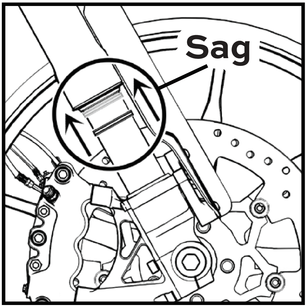
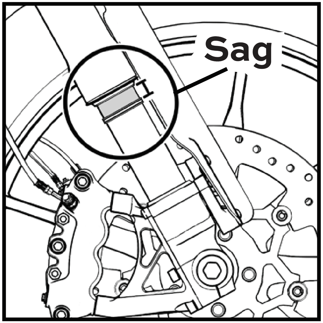
PRELOAD Where Should It Be?
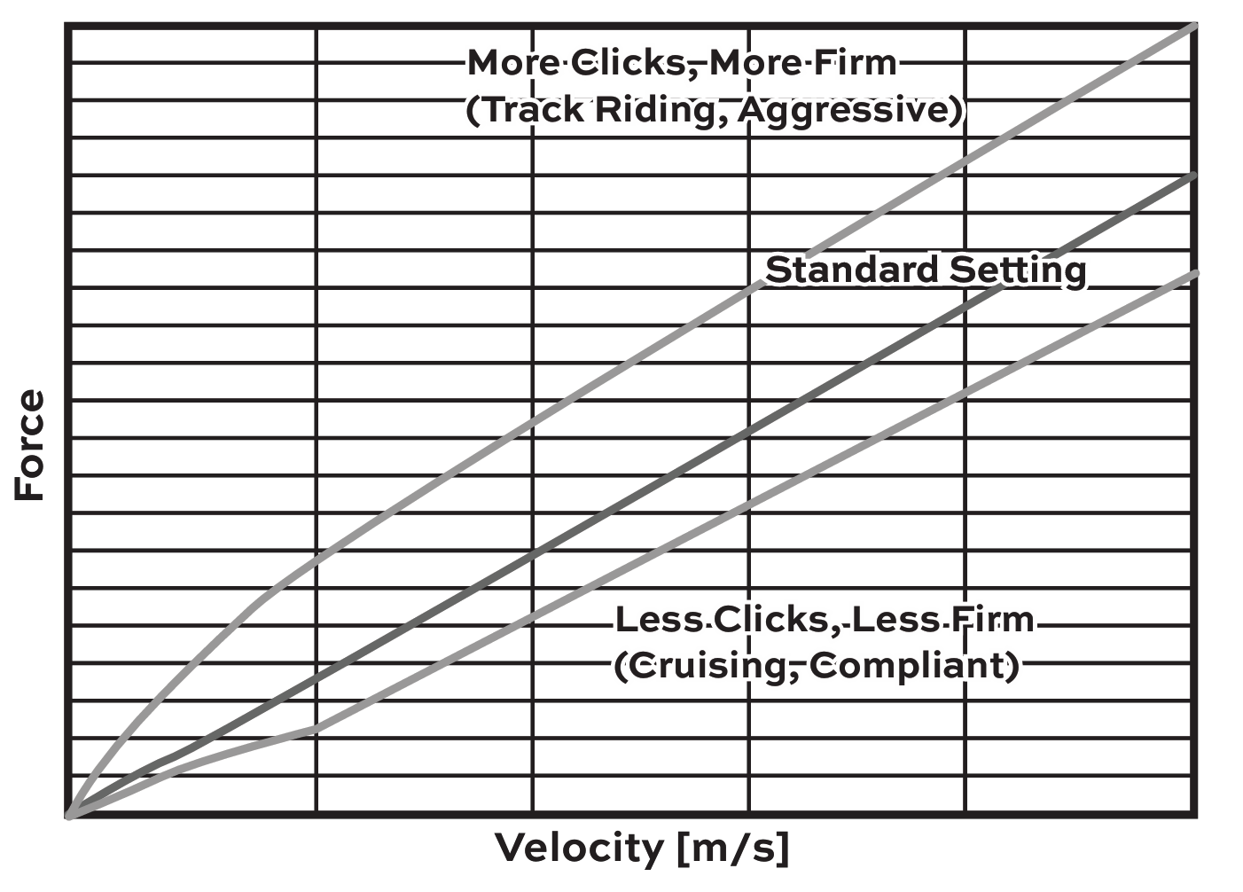
Time to fine tune for your riding style. Your forks have Compression (COM) and Rebound (REB) adjustment on your cap (3mm brass allen adjusters). These adjust the firmness of your ride.
The more they are turned in, the firmer the feedback. Standard setting is achieved by turning clockwise until it lightly seats/stops, then turned counter-clockwise 12 clicks. When fine tuning it's suggested to make 2 clicks at a time, then test ride.
STEP 3 - FINISHING UP THE INSTALLATION:
CUT TEMPLATES:
Road King
- The Road King Nacelle must be cut to fit over the edge of the tree.
Road Glide
- The Road Glide Nacelle may be left uncut if the fork adjuster is installed flush with the top of the top tree.
- Kraus recommends still cutting the nacelle as it allows for adjustment.
- Drilling a hole into the nacelle is recommend as it allows for easier adjustment and service for the fork, i.e., adjusting your preload, compression, and rebound setting.
NOTE: We recommend that you refer to your OEM manual for procedure, step by step run through, required tools and specifications to make sure all pieces and parts are properly installed! Go for a slow, careful test ride. Afterwords, double check all pieces, parts and systems.